Table of Contents
S7 Device Plugin
The S7 Device Plugin allows reading and writing values from physical SIMATIC S7 PLC devices via TCP/IP.
The following device types are supported:
- S7-1500 (see PLC Settings)
- S7-1200 (see PLC Settings)
- S7-300
- S7-400
- WinAC
- S7-SoftPLC
- LOGO! (see PLC Settings)
- S7-200
- SIMATIC S5 over S5-LAN
- S7-LAN
- VIPA-S7 and any other S7-TCP/IP compatible PLC
Features
- Optimized read and write requests by using the best utilization regarding the package size.
- Automated connection handling including auto-reconnect.
- Accessing PLC memory using user defined types.
- Use of existing PLC projects to set up channels and variables. The following project formats are supported:
- STEP7 Project Files (*.s7p)
- IP-S7 Project Files (*.ips7)
- S7 Watch Project Files (*.wproj)
- CSV-to-S7 Project Files (*.ini)
Purpose & Use Cases
Purpose
The linked devices can simply be controlled using CoDaBix®. By linking the PLC memory to the Nodes defined in CoDaBix® the PLC can directly interact with many other Nodes, devices, services, etc. maintained in CoDaBix®. Also other CoDaBix® participants can interact with the PLC devices linked through the S7 Device Plugin.
Use Cases
- Dynamic generation of manufacturing jobs based on different conditions and data produced by machines, users, orders, condition, services, etc.
- Additional reliability by monitoring the whole plant including inter-plant interaction
- Centralized controller and flow surveillance for early diagnosis of possible failures
- Possibilities to improve the Shop Floor Management by monitoring and recording production data produced by the devices
Installation
This plugin is part of the CoDaBix® Setup. Please consult CoDaBix® Setup and First Start for more information on how to install and uninstall this plugin.
Requirements
- Basic requirements of CoDaBix
- Enabled outgoing TCP/IP connection via port 102
PLC Settings
Please note that in order to access the S7-1200, S7-1500 and the LOGO!, the optimized data block access has to be deactivated at the data block attributes.
To do that, you can find instructions at: Deactivate optimized data block access.
Configuration
Using CoDaBix
The whole S7 Device Plugin configuration is located in the node path /System/Devices/S7 Device.

Channel
An S7 Device Channel represents the connection to a S7 PLC.
Settings
IP address or hostname of the S7 PLC.
Rack
The rack number of the PLC device.
Slot
The slot number of the PLC device.
Device Type
The device type of the SIMATIC S7 PLC. The following device types are supported:
- LOGO!
- S7-200
- S7-300
- S7-400
- S7-1200
- S7-1500
Channel Type
The type of device channel to use to communicate with the PLC.
DateTime Interpretation
Specifies how the timezone of read and written DateTime values should be interpreted (are the date/time values in the PLC stored as UTC time or as local time).
Solve Siemens PDU Bug
Specifies if a reduced PDU size should be used to work-around an issue in some S7-400 devices which would otherwise randomly truncate a large data packet, resulting in an error like “specified data area doesn't exist”.
Is Simulation
Specifies whether this device runs in simulation mode, which means no connection to a physical device is established.
Adding a Channel

To add a new S7 Channel, please follow these steps:
- Add a Folder Node within the node
S7 Device/Channels, or right-click on theS7 Device/Channelsnode and selectAdd Channel. - In the
Add Channeldialog, specify the settings for the S7 connection.
- After clicking on “Save”, the channel node is created.
- You can start the channel by selecting the channel node and clicking the start button.
Variables
Within the node Variables you can create datapoint nodes which can be read and written from/to the S7. Additionally, you can import variables e.g. from a STEP7 project.
The Value Type property must be set to the corresponding S7 Device type. Currently the following types are supported in the S7 Device Plugin:
| S7 Device Type | PLC Type | Preferred CoDaBix Value Type | Description |
|---|---|---|---|
Bool | BOOL | Boolean or Boolean-Array | A variable of the PLC type BOOL. |
Byte | BYTE | Byte or Byte-Array | A variable of the PLC type BYTE. |
Char | CHAR | String or String-Array | A variable of the PLC type CHAR. |
Int | INT | Int16 or Int16-Array | A variable of the PLC type INT. Representing a signed 16 bit integer. |
Word | WORD | UInt16 or UInt16-Array | A variable of the PLC type WORD. Representing an unsigned 16 bit integer. |
DInt | DINT | Int32 or Int32-Array | A variable of the PLC type DINT. Representing a signed 32 bit integer. |
DWord | DWORD | UInt32 or UInt32-Array | A variable of the PLC type DWORD. Representing an unsigned 32 bit integer. |
LInt | LINT | Int64 or Int64-Array | A variable of the PLC type LINT. Representing a signed 64 bit integer. |
LWord | LWORD | UInt64 or UInt64-Array | A variable of the PLC type LWORD. Representing an unsigned 64 bit integer. |
Real | REAL | Single or Single-Array | A variable of the PLC type REAL. Representing a single precision floating point number. |
Double | REAL | Double or Double-Array | A variable of the PLC type REAL. Representing a double precision floating point number. |
LReal | LREAL | Double or Double-Array | A variable of the PLC type LREAL. Representing a double precision floating point number. |
Date | DATE | DateTime or DateTime-Array | A variable of the PLC type DATE. |
Time | TIME | TimeSpan or TimeSpan-Array | A variable of the PLC type TIME. |
TimeOfDay | TOD/TIME_OF_DAY | TimeSpan or TimeSpan-Array | A variable of the PLC type TOD/TIME_OF_DAY. |
S5Time | S5TIME | TimeSpan or TimeSpan-Array | A variable of the PLC type S5TIME. |
DateTime | DT/DATE_AND_TIME | DateTime or DateTime-Array | A variable of the PLC type DT/DATE_AND_TIME. |
DateTimeLong | DTL | DateTime or DateTime-Array | A variable of the PLC type DTL. |
String | STRING | String | A variable of the PLC type STRING. |
S5String | BYTE | String | A variable of the PLC type BYTE. A fixed number of bytes is interpreted as string. |
Path
The Path property of the node is used to specify the address, optionally a type, and (for arrays or strings) the length:
<Address>
<Address>, <Length>
<Address>, <Type>
<Address>, <Type>[<Length>]
| Placeholder | Description |
|---|---|
<Address> | The address of the data. Example: DB10.DBW 16 |
<Length> | If the variable is an array or a string, specify the array/string length here. It will only be used for reading, because when writing an array/string, its length will be determined from the value that is written. |
<Type> | If present, contains the S7 Device Type (see table above) which will override the default type inferred from the CoDaBix Value Type. Note: When using CoDaBix Value Type Double, The S7 Device Type is not automatically inferred; you will need to specify Double explicitely. |
Examples
| CoDaBix Value Type | Path | Meaning |
|---|---|---|
Boolean | DB10.DBX 3.2 | Single bit (BOOL) at address DB10.DBX 3.2 |
Boolean-Array | DB10.DBX 3.4, 18 | Bit (BOOL) array from address DB10.DBX 3.4 to DB10.DBX 5.6 (exclusive) |
Int32 | DB10.DBD 12, DInt | Single DInt (DINT) at address DB10.DBW 12 |
Double-Array | DB10.DBD 20, Double[5] | Double-Array (REAL) from address DB10.DBD 20 to DB10.DBD 40 (exclusive) |
String | DB10.DBB 40, 100 | String (STRING) from address DB10.DBB 40 to DB10.DBB 142 (exclusive) |
String | DB10.DBB 40, S5String[100] | S5String (BYTE) from address DB10.DBB 40 to DB10.DBB 140 (exclusive) |
Import/Export
The S7 Device Plugins supports importing and exporting individual channels as S7 XML Configuration file (see next section). Additionally, you can import a STEP7 project (.s7p) that has been packed into a ZIP file into a channel.
The import and export options are shown when right-clicking on a specific channel:
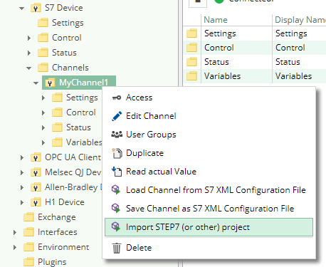
To import a configuration file or STEP7 project as a new channel, create a new channel first (with default settings), then right-click on the channel to open the import dialog.
Using the S7 XML Configuration File
Structure
The S7 Device Plugin defines the root of its element tree by the PluginSettings element as described in Plugin Configuration - Using a Configuration File and continues its XML tree using the Channel element.
Channel Element
The Channel element serves as the container for the elements Settings and Variables. One channel identifies one PLC connection to which the channel configuration belongs. This information is therefore used by the S7 Device Plugin to link the PLC to CoDaBix®.
The Channel element can look as follows:
<Channel>
  <Settings />
  <Variables />
</Channel>
Settings Element
The Settings element defines the attributes to setup the channel. These attributes configure the channels connection parameters.
The Settings element can look as follows:
<Settings Address="192.168.0.80"
          Rack="0"
          Slot="2"
          ChannelType="OperationPanel"
          DeviceType="S7400" />
The Settings element provides the following list of attributes:
| Mandatory | Type | Purpose | |
|---|---|---|---|
Address | yes | String | The IP Address of the PLC device to link. |
Rack | no | Int32 | The rack number of the PLC device. |
Slot | no | Int32 | The slot number of the PLC device. |
ChannelType | no | S7 Device Channel Type | The type of device channel to use to communicate with the PLC. |
DeviceType | no | S7 Device Type | The type of PLC device. |
S7 Device Channel Type
The following values are valid for attributes of that type:
| Value | Description |
|---|---|
“OperationPanel” | To connect via OP channel to the device. |
“ProgrammerDevice” | To connect via PG channel to the device. |
“Other” | To connect to the device using alternative channels. |
S7 Device Type
The following values are valid for attributes of that type:
| Value | Description |
|---|---|
“Logo” | SIEMENS LOGO! |
“S7200” | SIMATIC S7-200 |
“S7300” | SIMATIC S7-300 |
“S7400” | SIMATIC S7-400 |
“S71200” | SIMATIC S7-1200 |
“S71500” | SIMATIC S7-1500 |
Variables Element
The Variables element serves as the container for one or more Variable elements. This element maintains all variables associated with the channel.
The Variables element can look as follows:
<Variables>
  <!-- 0-n Variable elements -->
</Variables>
Variable Element
The Variable element serves as the container for the element Variables. One variable identifies one addressable area in the memory of the PLC or a set of subsequent variables identify multiple addressable areas in the memory of the PLC. This information is therefore used by the S7 Device Plugin to link the PLC memory to CoDaBix® Nodes.
Each Variable element provides the following list of attributes:
| Mandatory | Type | Purpose | |
|---|---|---|---|
Identifier | no | GUID | The generic unique identifier of the entitiy associated with the variable. This is a generic entity attribute, for more information about its usage see Plugin Configuration - Using a Configuration File: The Entities Identifier Attribute. |
ChangeType | no | ChangeType | The state of the entity configuration used to represent the variable. This is a generic entity attribute, for more information about its usage see Plugin Configuration - Using a Configuration File: The Entities ChangeType Attribute. |
Name | yes | String | The unique name (within the Variables element) of the variable. |
Description | no | String | The description of the usage and purpose of the addressed memory area. |
Address | yes | PLC Address | The operand to use to address the memory of the PLC (not supported in this case: Type=“Object”). |
Type | yes | PLC Variable Type | The type of data stored at the addressed memory and how it is to be interpreted. |
Length | no | Int32 | The length of an array or string variable (only supported on Type=“String” and numerical Types). If this attribute is defined the variable defines an array value (if supported), otherwise a scalar value. |
PLC Variable Type
The following values are valid for attributes of that type:
| Value | Description |
|---|---|
"Bool" | A variable of the PLC type BOOL. |
"Byte" | A variable of the PLC type BYTE. |
"Char" | A variable of the PLC type CHAR. |
"Int" | A variable of the PLC type INT. Representing a signed 16 bit integer. |
"Word" | A variable of the PLC type WORD. Representing an unsigned 16 bit integer. |
"DInt" | A variable of the PLC type DINT. Representing a signed 32 bit integer. |
"DWord" | A variable of the PLC type DWORD. Representing an unsigned 32 bit integer. |
"Real" | A variable of the PLC type REAL. Representing a single precision floating point number. |
"Double" | A variable of the PLC type REAL. Representing a double precision floating point number. |
"Date" | A variable of the PLC type DATE. |
"Time" | A variable of the PLC type TIME. |
"TimeOfDay" | A variable of the PLC type TOD/TIME_OF_DAY. |
"S5Time" | A variable of the PLC type S5TIME. |
"DateTime" | A variable of the PLC type DT/DATE_AND_TIME. |
"DateTimeLong" | A variable of the PLC type DTL. |
"String" | A variable of the PLC type STRING. |
"S5String" | A variable of the PLC type BYTE. A fixed number of bytes is interpreted as string. |
PLC Variable Address
The following Operand and Data Type combinations are valid to construct a valid PLC variable address:
Operands
| Operand | Siemens, DE | IEC |
|---|---|---|
| Input | E | I |
| Output | A | Q |
| Flag | M | M |
| Peripherals | P | P |
| Counter | Z | C |
| Data Block | DB | DB |
| Timer | T | T |
Data Types
| Data Type | Operand | Bits | Range | Description |
|---|---|---|---|---|
| BOOL | X | 1 | 0 to 1 | A single bit representing true (1) or false (0). |
| BYTE | B | 8 | 0 to 255 | An unsigned 8-bit integer. |
| WORD | W | 16 | 0 to 65.535 | An unsigned 16-bit integer (Word). |
| DWORD | D | 32 | 0 to 232 -1 | An unsigned 32-bit integer (Double Word). |
| CHAR | B | 8 | A+00 to A+ff | An ASCII-Code as an unsigned 8-bit character. |
| INT | W | 16 | -32.768 to 32.767 | A signed 16-bit integer. |
| DINT | D | 32 | -231 to 231-1 | A signed 32-bit integer (Double Word). |
| REAL | D | 32 | +-1.5e-45 to +-3.4e38 | An IEEE754 32-bit single precision floating point number. |
| S5TIME | W | 16 | 00.00:00:00.100 to 00.02:46:30.000 | A binary coded decimal (BCD) number representing a time span. |
| TIME | D | 32 | 00.00:00:00.000 to 24.20:31:23.647 | A signed 16-bit integer representing a time span in milliseconds. |
| TIME_OF_DAY | D | 32 | 00.00:00:00.000 to 00.23:59:59.999 | An unsigned 16-bit integer representing a time span in milliseconds. |
| DATE | W | 16 | 01.01.1990 to 31.12.2168 | An unsigned 16-bit integer representing a date in days. |
| DATE_AND_TIME | D | 64 | 00:00:00.000 01.01.1990 to 23:59:59.999 31.12.2089 | A binary coded decimal (BCD) number representing a date and time. |
Examples
| Example | Data type | Siemens | IEC |
|---|---|---|---|
| Input Byte 1, Bit 0 | BOOL | E 1.0 | I 1.0 |
| Output Byte 1, Bit 7 | BOOL | A 1.7 | Q 1.7 |
| Flag Byte 10, Bit 1 | BOOL | M 10.1 | M 10.1 |
| Data Block 1, Byte 1, Bit 0 | BOOL | DB1.DBX 1.0 | DB1.DBX 1.0 |
| Input Byte 1 | BYTE | EB 1 | IB 1 |
| Output Byte 10 | BYTE | AB 10 | QB 10 |
| Flag Byte 100 | BYTE | MB 100 | MB 100 |
| Peripherals Input Byte 0 | BYTE | PEB 0 | PIB 0 |
| Peripherals Output Byte 1 | BYTE | PAB 1 | PQB 1 |
| Data Block 1, Byte 1 | BYTE | DB1.DBB 1 | DB1.DBB 1 |
The Variable element can look as follows:
<Variable Name="Active Rotations"
          Type="DInt"
          Address="DB101.DBD 0" />
The Variable element with the Type attribute and the attibute value “Object” can look as follows:
<Variable Name="Mill Job No. 1" Description="Identifies the mill job no. 1" Type="Object">
  <Variables>
    <Variable Name="Rotations" Type="DInt" Address="DB200.DBD 0" />
    <Variable Name="Use Colling" Type="Bool" Address="DB200.DBX 4.0" />
    <Variable Name="Use Fan" Type="Bool" Address="DB200.DBX 4.1" />
    <Variable Name="Point 1" Type="Object">
      <Variables>
        <Variable Name="X" Description="The x portion of the drill." Type="Int" Address="DB200.DBW 5" />
        <Variable Name="Y" Description="The y portion of the drill." Type="Int" Address="DB200.DBW 7" />
      </Variables>
    </Variable>
    <Variable Name="Point 2" Type="Object">
      <Variables>
        <Variable Name="X" Description="The x portion of the drill." Type="Int" Address="DB200.DBW 9" />
        <Variable Name="Y" Description="The y portion of the drill." Type="Int" Address="DB200.DBW 11" />
      </Variables>
    </Variable>
    <Variable Name="Point 3" Type="Object">
      <Variables>
        <Variable Name="X" Description="The x portion of the drill." Type="Int" Address="DB200.DBW 13" />
        <Variable Name="Y" Description="The y portion of the drill." Type="Int" Address="DB200.DBW 15" />
      </Variables>
    </Variable>
  </Variables>
</Variable>
Usage
It is recommended to use a professional XML editor when editing the configuration file manually.
To also benefit from the XML scheme definition mentioned at the end of this article you have to refer to the scheme definition by using the xsi:noNamespaceSchemaLocation attribute in the document root element PluginSettings as follows (the XSD file needs to be placed next to the XML file):
<?xml version="1.0" encoding="utf-8" ?>
<PluginSettings xmlns:xsi="http://www.w3.org/2001/XMLSchema-instance"
                xsi:noNamespaceSchemaLocation="CoDaBix.S7DevicePlugin.Settings.xsd">
  <!-- child elements -->
</PluginSettings>
Independent from editing / creating the configuration file manually or automated, the element tree above documented must be fulfilled to produce a valid, well-formed and usable configuration file.
Synchronization
An S7 XML Configuration file is assigned to a S7 Device Channel in CoDaBix for automatic synchronization, if the following condition is true:
- A file with the name
CoDaBix.S7DevicePlugin.<ChannelName>.Settings.xmlexists in the ConfigFolder (<CodabixProjectDir>/plugins/S7DevicePlugin) when starting the S7 Plugin (i.e. when starting CoDaBix) or when creating a new channel in CoDaBix.
In that case, once the configuration file changes, it is automatically synchronized into CoDaBix. Also, when the variables in CoDaBix (or the channel settings) are changed, the changes are synchronized into the configuration file.
Regardless of the automatic synchronization, you can also use manual synchronization by right-clicking on a S7 Device Channel in CoDaBix and selecting the corresponding Import/Export menu item.
Example Configuration File
- CoDaBix.S7DevicePlugin.Settings.xml
<?xml version="1.0" encoding="utf-8"?>
<PluginSettings>
  <Channel>
    <Settings Address="192.168.0.80" ChannelType="OperationPanel" DeviceType="S7400" />
    <Variables>
      <Variable Name="Active Job Name" Type="String" Address="DB100.DBB 0" Length="64" />
      <Variable Name="Active Job Number" Type="String" Address="DB100.DBB 80" Length="8" />
      <Variable Name="Active Rotations" Type="DInt" Address="DB101.DBD 0" />
      <Variable Name="Mill Job No. 1" Description="Identifies the mill job no. 1" Type="Object">
        <Variables>
          <Variable Name="Rotations" Type="DInt" Address="DB200.DBD 0" />
          <Variable Name="Use Colling" Type="Bool" Address="DB200.DBX 4.0" />
          <Variable Name="Use Fan" Type="Bool" Address="DB200.DBX 4.1" />
          <Variable Name="Point 1" Type="Object">
            <Variables>
              <Variable Name="X" Description="The x portion of the drill." Type="Int" Address="DB200.DBW 5" />
              <Variable Name="Y" Description="The y portion of the drill." Type="Int" Address="DB200.DBW 7" />
            </Variables>
          </Variable>
          <Variable Name="Point 2" Type="Object">
            <Variables>
              <Variable Name="X" Description="The x portion of the drill." Type="Int" Address="DB200.DBW 9" />
              <Variable Name="Y" Description="The y portion of the drill." Type="Int" Address="DB200.DBW 11" />
            </Variables>
          </Variable>
          <Variable Name="Point 3" Type="Object">
            <Variables>
              <Variable Name="X" Description="The x portion of the drill." Type="Int" Address="DB200.DBW 13" />
              <Variable Name="Y" Description="The y portion of the drill." Type="Int" Address="DB200.DBW 15" />
            </Variables>
          </Variable>
        </Variables>
      </Variable>
    </Variables>
  </Channel>
</PluginSettings>
Example Configuration Scheme File
- CoDaBix.S7DevicePlugin.Settings.xsd
<?xml version="1.0" encoding="utf-8"?>
<xs:schema id="CoDaBix.S7DevicePlugin.Settings"
           elementFormDefault="qualified"
           xmlns:xs="http://www.w3.org/2001/XMLSchema">
  <xs:simpleType name="Guid">
    <xs:restriction base="xs:string">
      <xs:pattern value="([0-9a-fA-F]{8}-[0-9a-fA-F]{4}-[0-9a-fA-F]{4}-[0-9a-fA-F]{4}-[0-9a-fA-F]{12})|(\{[0-9a-fA-F]{8}-[0-9a-fA-F]{4}-[0-9a-fA-F]{4}-[0-9a-fA-F]{4}-[0-9a-fA-F]{12}\})"/>
    </xs:restriction>
  </xs:simpleType>

  <xs:simpleType name="PlcAddress">
    <xs:restriction base="xs:string">
      <xs:pattern value="^[ \t]*((DB[ \t]*([\d]+)[ \t]*\.[ \t]*(DB))|(((Z|C)|DB|M|(E|I)|L|(A|Q)|(PE|PI)|(PA|PQ)|T)))[ \t]*((X|B|W|D))?[ \t]*([\d]+)(\.([\d]+))?\b" />
    </xs:restriction>
  </xs:simpleType>

  <xs:simpleType name="VariableEnumType">
    <xs:restriction base="xs:string">
      <xs:enumeration value="Bool" />
      <xs:enumeration value="Byte" />
      <xs:enumeration value="Char" />
      <xs:enumeration value="Int" />
      <xs:enumeration value="Word" />
      <xs:enumeration value="DInt" />
      <xs:enumeration value="DWord" />
      <xs:enumeration value="Real" />
      <xs:enumeration value="Double" />
      <xs:enumeration value="Date" />
      <xs:enumeration value="Time" />
      <xs:enumeration value="TimeOfDay" />
      <xs:enumeration value="S5Time" />
      <xs:enumeration value="DateTime" />
      <xs:enumeration value="String" />
      <xs:enumeration value="S5String" />
    </xs:restriction>
  </xs:simpleType>

  <xs:complexType name="VariableType">
    <xs:sequence>
      <xs:element name="Variables" type="VariablesType" minOccurs="0" maxOccurs="1" />
    </xs:sequence>

    <xs:attribute name="Identifier" type="Guid" use="required" />
    <xs:attribute name="Name" type="xs:string" use="required" />
    <xs:attribute name="Description" type="xs:string" use="optional" />
    <xs:attribute name="Address" type="PlcAddress" use="optional" />
    <xs:attribute name="Type" type="VariableEnumType" use="required" />
    <xs:attribute name="Length" type="xs:integer" use="optional" default="-1" />
  </xs:complexType>

  <xs:complexType name="VariablesType">
    <xs:sequence>
      <xs:element name="Variable" type="VariableType" minOccurs="0" maxOccurs="unbounded" />
    </xs:sequence>
  </xs:complexType>

  <xs:simpleType name="ChannelDeviceEnumType">
    <xs:restriction base="xs:string">
      <xs:enumeration value="Logo" />
      <xs:enumeration value="S7200" />
      <xs:enumeration value="S7300" />
      <xs:enumeration value="S7400" />
      <xs:enumeration value="S71200" />
      <xs:enumeration value="S71500" />
    </xs:restriction>
  </xs:simpleType>

  <xs:simpleType name="ChannelEnumType">
    <xs:restriction base="xs:string">
      <xs:enumeration value="OperationPanel" />
      <xs:enumeration value="ProgrammerDevice" />
      <xs:enumeration value="Other" />
    </xs:restriction>
  </xs:simpleType>

  <xs:complexType name="ChannelSettingsType">
    <xs:attribute name="Address" type="xs:string" use="required" />
    <xs:attribute name="Rack" type="xs:integer" use="optional" default="0" />
    <xs:attribute name="Slot" type="xs:integer" use="optional" default="2" />
    <xs:attribute name="ChannelType" type="ChannelEnumType" use="optional" default="OperationPanel" />
    <xs:attribute name="DeviceType" type="ChannelDeviceEnumType" use="optional" default="S7300" />
  </xs:complexType>

  <xs:complexType name="ChannelType">
    <xs:sequence>
      <xs:element name="Settings" type="ChannelSettingsType" minOccurs="0" maxOccurs="1" />
      <xs:element name="Variables" type="VariablesType" minOccurs="0" maxOccurs="1" />
    </xs:sequence>
  </xs:complexType>

  <xs:complexType name="PluginSettingsType">
    <xs:sequence>
      <xs:element name="Channel" type="ChannelType" minOccurs="0" maxOccurs="1" />
    </xs:sequence>
  </xs:complexType>

  <xs:element name="PluginSettings" type="PluginSettingsType" />
</xs:schema>
Using the Application (Windows only)
Note: The configuration application allows you to load and save S7 XML Configuration Files (.xml) that can be imported and exported on a
S7 Device Channel in CoDaBix (using the context menu), or that are assigned to an CoDaBix S7 Device Channel for automatic
synchronization (see section Using the S7 XML Configuration File).
The configuration application resides in the folder <CodabixInstallDir> and is started by double-clicking the file with the name CoDaBix.S7DevicePlugin.Configurator.exe.
Overview

Usage
- Add a new
Channelin the left list by clicking the upper plus button.- Set the name of the channel by clicking its name in the right pane.
- Set up the
Channel Settingslike theIP Address(at least required). - Optionally set the appropriate
Device Typeand select theChannel Typeto be used. - Optionally set the
RackandSlot(in case it differs from the defaults).
- Add a new
Variableto theChannelin the second from the left list by clicking the upper first button with the plus sign.- Set up the name of the variable by clicking its name in the right pane.
- Optionally set the description of the variable by clicking in the free area beneath the variable name.
- Set up the PLC address operand to be used to access the PLC memory for that variable.
- Set up the PLC variable type in the combo and enter, in case of a string or an array (check the option
Is Array) variable, the appropriate length of the variable. - Optionally add additional variables in case the previously added variable is of the type “Object”. Do that by selecting the object variable in the left tree and then click the second add button with the plus sign above.
- To remove a variable, select it in the tree and click on the button with the minus sign above.
- To remove a channel, select it in the left list and click on the button with the minus sign above.
- Using the
Import Projectbutton it is possible to import the following project formats:- STEP7 Project Files (*.s7p)
- IP-S7 Project Files (*.ips7)
- S7 Watch Project Files (*.wproj)
- CSV-to-S7 Project Files (*.ini)
Diagnostics
Channel
To monitor and diagnose the status of a S7 Channel, take a look at the following image:
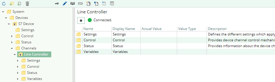
The image above depicts the S Channel's Control Panel which displays all status relevant information. The control panel will automatically update its status information when a new status is available.
Status Circle
| Color | Meaning |
|---|---|
 | The channel is stopped. Click the ► button to start it. |
 | The channel is currently in the progress of starting or stopping or is waiting to establish a connection. |
 | The channel is running and a connection has successfully been established. You can stop it by clicking the ◼ button. |
 | The channel is running, but the connection is currently in an error state. Please check the status text for more information. |
Variables
To monitor and diagnose the status of the different S7 variables take a look at the variable's Status Code property displayed in CoDaBix®.
In case the Status Code column displays the value Bad in most cases the addressed data area is not accessible.

Log File
All device channel related status information is also logged into the channel-specific log file stored in the [LoggingFolder].
Each log file is named in the naming scheme S7 Device.<ChannelName>.log. The content of such a log file can look as follows:
...
[15:31:46 05.09.2016] - Error (Severity=High): Code=[-6], Text=[The specified CPU could not be found.]
...
Using the sample channel the name of the log file would be: S7 Device.Line Controller.log
Status Codes
The following table displays the different status information possible:
| Code | Category | Severity | Text |
|---|---|---|---|
| -88 | Error | High | The operation has been canceled. |
| -34 | Error | High | The requested PLC block could not be found. |
| -33 | Error | High | The PLC does not support bit based operations. |
| -32 | Error | High | The PLC supplied truncated data. |
| -31 | Error | High | The requested PLC or PC type of data can not be transformed from one to the other. |
| -30 | Error | High | The requested PLC or PC type of data is not available. |
| -21 | Error | High | A connection to the device has already been established. |
| -20 | Error | High | The size of the supplied buffer is lower than the amount of data available. |
| -11 | Error | High | The type or format of data supplied is not supported. |
| -10 | Error | High | The supplied access mode is not supported or unknown. |
| -9 | Error | High | The operation failed upon a value range error. |
| -8 | Error | High | Failed to allocate required memory. |
| -7 | Error | High | The operation failed upon a socket error. |
| -6 | Error | High | The specified CPU could not be found. |
| -5 | Error | High | A general error occurred. |
| -2 | Error | High | The necessary memory could not be allocated (out of memory). |
| -1 | Error | High | The operation has timed out. |
| 0 | Information | Moderate | The operation completed without any kind of error. |
| 1 | Information | Moderate | The operation completed successfully. |
| 2 | Information | Moderate | The addressed data area does not exist. |
Entities
As each device plugin the S7 device plugin extends the basic CoDaBix Device Model.
Device
The plugin's device type S7Device also defines the S7DeviceChannel and therefore extends the basic CodabixDevice and CodabixDeviceChannel entities. While the S7Device just represents a concretization of the CodabixDevice, the S7DeviceChannel extends the CodabixDeviceChannel with the S7 Variable Entities.
Channel
Each channel is handled by a Channel Worker which establishes a physical connection to the S7 device.
For diagnostic purposes, the worker automatically reads the PLC address “MB 0” every 10 seconds to update the status code of the Channel and description to detect connection failures.
By default, the worker does not read any values. When a client or plugin requests a synchronous read of the Channel variables in CoDaBix (e.g. using the CoDaBix Web Configuration's function “Read actual value”), the channel worker reads them from the underlying S7 device and then writes them into the corresponding CoDaBix Nodes.
Similarly, when a Client or plugin writes values into the channel's variables, the channel worker will write those values to the underlying S7 device.
To have an S7 variable being read steadily, you can edit the Node in the CoDaBix Web Configuration and set “History Options” to Yes (which will create an internal subscription), or you can use e.g. a OPC UA Client connected to the OPC UA Server plugin and create a subscription for the S7 variable Nodes. In these cases, the channel worker reads the variables from the S7 at a regular interval and, if the value of one of the variables has changed, writes the new value into the corresponding CoDaBix Node.
Variable
Each S7 variable can access the same PLC memory using the same PLC address operand.
However, its interpretation depends on the PLC Data Type selection. Supported variable formats are scalar, array and object variables. Variables of the type Object can own further variables and are defined as UserDefinedTypes (UDT in STEP7).
Folders & Files
Folders
| Content | Path | Usage |
|---|---|---|
| AssemblyFolder | <CodabixInstallDir>/plugins/S7DevicePlugin/ | Contains the plugin's assembly file. |
| ConfigFolder | <CodabixDataDir>/plugins/S7DevicePlugin/ | Contains the plugin's configuration file. |
| LoggingFolder | <CodabixDataDir>/log/ | Contains the plugin's log files. |
Files
| Type | Path | Usage |
|---|---|---|
| Assembly | [AssemblyFolder]/CoDaBix.S7DevicePlugin.dll | The plugin's assembly file. |
| Config App | <CodabixInstallDir>/CoDaBix.S7DevicePlugin.Configurator.exe | The config application file. |
| Config File | [ConfigFolder]/CoDaBix.S7DevicePlugin.<ChannelName>.Settings.xml | The optional channel config file. |
| Logging | [LoggingFolder]/S7 Device.<ChannelName>.log | The log file. |
About Versions
This Document
| Date | 2020-12-01 |
|---|---|
| Version | 1.3 |
Plugin
| Name | S7 Device Plugin |
|---|---|
| Node | /System/Devices/S7 Device |
| Version | 1.2.0 |
Assembly
| Name | CoDaBix.S7DevicePlugin.dll |
|---|---|
| Date | 2020-12-01 |
| Version | 1.2.0.0 |