Table of Contents
H1 Device Plugin
The H1 Device Plugin allows reading and writing values from SIMATIC S5 PLC devices using the SINEC H1 protocol based on ISO/MAC (Industrial Ethernet).
Prerequisites
- This plugin is currently available only with Codabix for Windows (x64 and x86).
- To use this plugin, WinPcap 4.1.3 must be installed.
Configuration
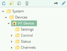
The whole H1 Device Plugin configuration is located in the node path /System/Devices/H1 Device.
Channel
An H1 Device Channel represents the connection to a H1 PLC.
Settings
Network Adapter
The NIC that should be used for the network communication.
MAC Address
The MAC address of the remote device.
Read SSAP/DSAP
The SSAP (Source SAP) and DSAP (Destination SAP) values that should be used when reading data. A maximum of 8 characters will be used.
Write SSAP/DSAP
The SSAP (Source SAP) and DSAP (Destination SAP) values that should be used when writing data. A maximum of 8 characters will be used.
Passive Mode
Specifies which party initiates the connection:
No: The local machine initiates the connection.Yes: The remote device initiates the connection.
Adding a Channel

To add a new H1 Channel, please follow these steps:
- Add a Folder Node within the node
H1 Device/Channels, or right-click on theH1 Device/Channelsnode and selectAdd Channel. - In the
Add Channeldialog, specify the settings for the H1 connection.
- After clicking on “Save”, the channel node is created.
- You can start the channel by selecting the channel node and clicking the start button.
Variables
Within the node Variables you can create datapoint nodes which can be read and written from/to the PLC.
The Value Type property must be set to the corresponding operand type. Currently the following types are supported:
| CoDaBix Type | Operand |
|---|---|
Boolean or Boolean-Array | X |
Byte/SByte or Byte-Array/SByte-Array | L (left=high byte) or R (right=low byte) |
Int16/UInt16 or Int16-Array/UInt16-Array | W |
Int32/UInt32 or Int32-Array/UInt32-Array | D |
Float or Float-Array | D |
TimeSpan or TimeSpan-Array | W |
Note: 32-bit values (Float, Int32) will be read/written using two separate (16-bit) words. This can mean that if the value changes in the PLC while reading it, you might get an inconsistent value when one word has the new value but the other one has the old value.
Note: Bit values (Boolean) will be read/written as (16-bit) word. When writing such a boolean value, the word will be read from the PLC, then the bit(s) will be changed, and then the word will be written back to the PLC. This can mean that if at the same time some other party changes another bit in that word, that change might get lost.
Path
The Path property of the node is used to specify the address and optionally the type and/or (for arrays) the length of the data. Currently, only Data Block (DB) is supported as data area.
DB<DB number>.D<Operand> <Offset>
DB<DB number>.D<Operand> <Offset>, <Length>
DB<DB number>.D<Operand> <Offset>, <Type>[<Length>]
DB<DB number>.DX <Offset>.<Bit>, <Length>
| Placeholder | Description |
|---|---|
<DB number> | The number of the data block. |
<Operand> | One of the operands as specified in the above table. |
<Offset> | The word (16-bit) offset from where the data should be accessed. |
<Bit> | When using a Boolean/Boolean-Array value you can specify the bit number in the word from 0 to 15. |
<Length> | The length of the array. |
<Type> | When using integer types, you can optionally specify a BCD type (Binary Coded Decimal) to store the values using BCD encoding. You can specify one of the following values: • BCD: The value is BCD-encoded. |
Examples
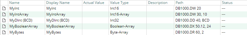
| Value Type | Path | Meaning |
|---|---|---|
Int16 | DB1000.DW 20 | In Data Block 1000, access the word at offset 20. |
Int16-Array | DB1000.DW 30, 10 | In Data Block 1000, start at offset 30 and read/write 10 words (exclusive end offset: 40). |
Int32 | DB1000.DD 40, BCD[4] | In Data Block 1000, start at offset 40 and read/write four 32-bit values (exclusive end offset: 48) and decode/encode the values as BCD. |
Boolean-Array | DB1000.DX 50.12, 24 | In Data Block 1000, access the bits from offset 50.12 to (exclusive) offset 52.4 (the bits are read/written as three 16-bit words). |
Byte-Array | DB1000.DR 60, 2 | In Data Block 1000, access the bytes from offset 60 (low byte) and 61 (high byte) |
Diagnostics
The H1 Device Plugin provides different status information depending on the layer to inspect. In general the channel-based diagnostic information is produced by the connection status of the channel to the PLC. The variable-based diagnostic information is produced during the read/write access of the different variables.
Channel
To monitor and diagnose the status of a H1 Channel, take a look at the following image:
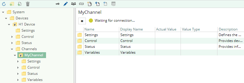
The image above depicts the H1 Channel's Control Panel which displays all status relevant information. The control panel will automatically update its status information when a new status is available.
Status Circle
| Color | Meaning |
|---|---|
 | The channel is stopped. Click the ► button to start it. |
 | The channel is currently in the progress of starting or stopping or is waiting to establish a connection. |
 | The channel is ready for doing read/write operations. You can stop it by clicking the ◼ button. |
 | The channel is running, but the connection is currently in an error state. Please check the status text for more information. |
Variables
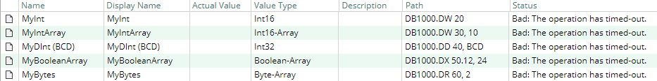
To monitor and diagnose the status of the different variables, take a look at the variable's Status property displayed in CoDaBix. Use the button “Read actual Value” to read the values from the PLC and store the result into the variables.
Log file
All channel related status information is also logged into the channel-specific log file stored in the [LoggingFolder]. Each log file is named in the naming scheme H1 Device.<ChannelName>.log.
The content of such a log file can look as follows:
...
2018-04-11 11:32:37.0 +2: [Error] Error (Severity=High): Code=[-1], Text=[The operation has timed-out.], Details=[]
...
Entities
Like every device plugin the H1 Device Plugin extends the basic CoDaBix Device Model.
Device
The plugin's device type H1Device also defines the H1DeviceChannel and therefore extends the basic CodabixDevice and CodabixDeviceChannel entities. While the H1Device just represents a concretization of the CodabixDevice, the H1DeviceChannel extends the CodabixDeviceChannel with the H1 Variable Entities.
Channel
Each channel is handled by a channel worker which establishes a network connection to the PLC.
By default, the worker does not read any values. When a client or plugin requests a synchronous read of the channel's variables in CoDaBix (e.g. using the CoDaBix Web Configuration's function “Read actual value”), the channel worker reads them from the underlying PLC and then writes them into the corresponding CoDaBix Nodes.
Similarly, when a client or plugin writes values into the channel's variables, the channel worker will write those values to the underlying PLC.
To have an H1 variable being read steadily, you can edit the Node in the CoDaBix Web Configuration and set “History Options” to Yes (which will create an internal subscription), or you can use e.g. a OPC UA Client connected to the OPC UA Server plugin and create a subscription for the H1 variable Nodes. In these cases, the channel worker reads the variables from the PLC at a regular interval and, if the value of one of the variables has changed, writes the new value into the corresponding CoDaBix Node.
Folders & Files
Folders
| Content | Path | Usage |
|---|---|---|
| AssemblyFolder | <CodabixInstallDir>/plugins/H1DevicePlugin/ | Contains the plugin's assembly file. |
| ConfigFolder | <CodabixProjectDir>/plugins/H1DevicePlugin/ | Contains the plugin's configuration file. |
| LoggingFolder | <CodabixProjectDir>/log/ | Contains the plugin's log files. |
Files
| Type | Path | Usage |
|---|---|---|
| Assembly | [AssemblyFolder]/CoDaBix.H1DevicePlugin.dll | The plugin's assembly file. |
| Logging | [LoggingFolder]/H1 Device.<ChannelName>.log | The log file. |
About Versions
This Document
| Date | 2020-01-07 |
|---|---|
| Version | 1.0 |
Plugin
| Name | H1 Device Plugin |
|---|---|
| Node | /System/Devices/H1 Device |
| Version | 1.0.0 |
Assembly
| Name | CoDaBix.H1DevicePlugin.dll |
|---|---|
| Date | 2020-01-07 |
| Version | 1.0.0.0 |